Thursday, July 21, 2011

Functionality of Different LTE Nodes

LTE Architecture
LTE network compromises of the following nodes:

  • UE (User Endpoint)
  • MME (Mobile Management Entity)
  • S-GW (Serving Gateway)
  • P-GW (PDN Gateway)
  • PDN (Packet Data Network or IP world)
  • PCRF (Policy and Charging Enforcement Function
  • eNB (e Node B)
  • SGSN (Serving GPRS Support Node)
  • HSS (Home Subscriber SubSystem)
  • E-UTRAN (Collection of eNB)
  • EPC (Combination of MME, S-GWand P-GW)
The Architecture of LTE network look like this:
LTE Non-Roaming architecture
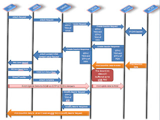
The communication between different nodes of LTE work like this:

We will go deeper to describe about the different interface between different nodes, functionality and the layering structure of LTE Nodes.

Interfaces between different Nodes:
Uu-Interface: This interface is in between UE and eNB. This is a radio/air interface and OFDMA (Orthogonal Frequency Division Multiple access) technology is used to send uplink packet and SC-FDMA technology is being used to send downlink packet.

X2-Interface: This interface is in between eNB and eNB. Under this interface the UDP being used as Transport protocol and GTP being used as Application protocol. Basically this interface is used for Handover.


S1-U Interface: This interface is in between eNB and S-GW and this interface will be used for data path communication. Under this interface  UDP will be used as Transport protocol and GTP-U protocol will be used for application protocol

S1-AP Interface: This interface is in between eNB and MME. This interface is used for sending signalling packet between eNB and MME. Under this interface SCTP will be used as transport protocol and S1-AP will be used as application protocol.
S11 Interface: This interface is in between MME and S-GW. this interface will be used for Signalling communication between MME and S-GW. Under this interface UDP will be used as transport protocol and GTP-C will be used as application protocol.

S5-C Interface: This interface is in between S-GW and P-GW. This interface will be used for signalling between S-GW and P-GW. Under this interface UDP will be used for transport protocol and GTP-C will be used for applicatio protocol.

S5-U Interface: This interface is in between S-GW and P-GW. This interface will be used for data path. Under this interface UDP will be used for transport protocol and GTP-U will be used for application protocol.
S6a Interface: This interface is in between MME and HSS. This interface will be used for Authentication, Authorization and Accounting. The SCTP will be used for transport protocol and Diameter will be used for application protocol.
 Functionality of LTE Nodes:
eNodeB
The following functionality for eNodeB in LTE network:

-     Header compression and user plane ciphering;
-     MME selection when no routing to an MME can be determined from the information provided by the UE;
-     UL bearer level rate enforcement based on UE-AMBR and MBR via means of uplink scheduling
(e.g. by limiting the amount of UL resources granted per UE over time);
-     DL bearer level rate enforcement based on UE-AMBR;
-     UL and DL bearer level admission control;
-     Transport level packet marking in the uplink, e.g. setting the DiffServ Code Point, based on the QCI of the associated EPS bearer;
-     ECN-based congestion control.


MME
The different functionality of MME are:

-     NAS signalling;
-     NAS signalling security;
-     Inter CN node signalling for mobility between 3GPP access networks (terminating S3);
-     UE Reachability in ECM-IDLE state (including control and execution of paging retransmission);
-     Tracking Area list management;
-     Mapping from UE location (e.g. TAI) to time zone, and signalling a UE time zone change associated with mobility,
-     PDN GW and Serving GW selection;
-     MME selection for handovers with MME change;
-     SGSN selection for handovers to 2G or 3G 3GPP access networks;
-     Roaming (S6a towards home HSS);
-     Authentication;
-     Authorization;
-     Bearer management functions including dedicated bearer establishment;
-     Lawful Interception of signalling traffic;
-     Warning message transfer function (including selection of appropriate eNodeB);
-     UE Reachability procedures.


Tuesday, July 19, 2011

GTP-C message description in LTE enviornment.

When you come across GTP-C message then you are surely curious about the GTP-C message handling in LTE network.
GTP-C message flows between different interface to setup the signalling connection. The interfaces are S11, S5, S8 and S4.

There are two type of GTP-C messages are there.
1. Path management messages
2. Tunnel management messages.

1. Path Management Messages
ECHO request/response will be used to ping destination GTP end point as well handle the restart procedure of a GTP endpoint.
Please refer ECHO message handling in GTP-C

2. Tunnel Management Messages
Different GTP-C messages are used to manage a Tunnel. The GTP-C messages are Create Session Request/Response, Create Bearer Request/Response, Modify Bearer Request/Response, Update Bearer Request/Response, Delete Session Request/Response, Delete Bearer Request/Response etc.

Let's see the following diagram where GTP-C message is used for signalling setup.
This figure is for attaching a UE in the LTE network

Here i will explain more on the GTP-C message flow in LTE Network.
a. Create Session Request/Response
This message is used to do signalling setup between MME and SGW or SGW and PGW.

To Create a tunnel between MME and SGW, MME sends Create Session Request towards SGW with GTP-C F-TEID, Bearer Context, MME FQ-CSID and some more Informational element.

The initial Create Session request from MME will have TEID value as 0 in the GTP-C header as MME doesn't know about the SGW F-TEID.
But further Create Session Request from MME will have TEID in GTP-C header as MME knows the TEID of S-GW.

The different Informational Elements of Create Session request are:
IMSI, MSISDN, User Location Information (ULI), Serving Network, RAT Type, Indication Flags, MME/SGW F-TEID, PGW F-TEID, PDN Type, PAA, Bearer Context to be created, Bearer Context to be removed, Recovery, MME-FQ-CSID, SGW-FQ-CSID, Charging Characteristics, Private Extension.
IMSI: The 15 digit number of UE.
MSISDN: The mobile no of UE.
MME/SGW F-TEID: This IE is MME S11 GTP-C(Control plane) F-TEID if MME sends Create Session Request towards S-GW and SGW S5 GTP-C(Control plane) F-TEID if SGW sends Create Session Request towards P-GW.
Bearer Context To be Created: This informational elements is for creating a default bearer through Create Session Request. It carry some sub Informational element. The Informational elements are:

  • EBI: Default bearer ID

Monday, July 18, 2011

ECHO message handling in GTP-C

Introduction: 
ECHO message is a primary message communication in GTP interface. This message is used for to ping an end point as well used for restoration procedure for an end point. We will go detail in the following description.

Format of ECHO message:


Bits
Octets

8
7
6
5
4
3
2
1
1

Version
P
T=0
Spare
Spare
Spare
2

Message Type
3

Message Length (1st Octet)
4

Message Length (2nd Octet)
5

Sequence Number (1st Octet)
6

Sequence Number (2nd Octet)
7

Sequence Number (3rd Octet)
8

Spare


This message is same as other GTP-C message header format but only one difference is the 4 bytes TEID filed is missing in the header format.

The ECHO message is also called as path management message in the GTP interface because this message is used for to ping an GTP endpoint in the S11, S5, S8 interfaces.

As well this message is used for restart procedure.

The format of GTP-C ECHO message is like this:

ECHO message is a combination of ECHO GTP-C header and some Informational Element.
The Informational elements are

Information elements
P
Condition / Comment
IE Type
Ins.
Recovery
M

Recovery
0
Sending Node Features
CO
This IE shall be sent towards a peer node on any GTPv2 interface if the sending node supports at least one feature on this interface or if the sending node supports at least one feature and does not know the interface type towards the peer node. This IE may be present otherwise.
Node Features
0
Private Extension
O

Private Extension
VS


This message contains one IE called Recovery IE to set the restart counter value for an GTP endpoint.

Suppose one GTP endpoint restarted then that end point will send an ECHO request to the other GTP end point  with the recovery IE.

Restart procedure Handling at SGW


During or immediately after an SGW Restart the SGW shall place local SGW restart counter value in all GTPv2 Echo requests/responses messages.

The SGW will receive the MME restart counter in GTPv2 Echo requests and Echo response messages that the SGW receives from the MME.

The SGW will receive the PGW restart counter in GTPv2 Echo requests/ responses receives from the PGW.
When an SGW detects that a peer MME has restarted it shall delete all PDN connection table data associated with the peer node that fails as well as freeing any internal SGW resources associated with those PDN connections.

When an SGW detects that a peer PGW has restarted it shall delete all PDN connection table data associated with the peer node that fails as well as freeing any internal SGW resources associated with those PDN connections. In addition, if the optional feature PGW Restart Notification is supported by the SGW  the SGW shall initiate the cleanup of the hanging PDN connections associated with the SGW and the restarted PGW at the corresponding MMEs by sending GTPv2 message(s) PGW Restart Notification, with the control plane IP address of the restarted PGW and the control plane IP address of the SGW on the S11 interface included

When the MME receives this message, according to the control plane IP address of the restarted PGW and the control plane IP address of the SGW on the S11 interface included in the message, MME should delete all PDN connection table data associated with the SGW and the restarted PGW as well as freeing any internal MME resources associated with those PDN connections. The MME may optionally perform other implementation specific actions such as to clear external resources (e.g. S1-MME messages to clear eNodeB resources) or more advanced forms of restoration. 


Restart procedure Handling at PGW


After a PGW restart, the PGW shall delete all MM Bearer contexts affected by the restart that it may have stored.
During or immediately after a PGW Restart, the PGW shall place this PGW restart counter value in all GTPv2 echo requests/responses the PGW sends.
The PGW will receive the SGW  restart counters in GTPv2 echo requests/responses. When a PGW detects that a peer SGW has restarted it shall delete all PDN connection table data associated with the peer node that fails as well as freeing any internal PGW resources associated with those PDN connections. 


Tuesday, July 12, 2011

GTP-C Overview

GTP-C tunnels are used between two nodes communicating over a GTP based interface, to separate traffic into different communication flows.
A GTP-C tunnel is identified in each node with a TEID, an IP address and a UDP port number. 
Each node will be uniquly identified by F-TEID (Fully Qualified Tunnel identifier) in a global network. Each node will share their   TEID for both signalling and Data path.


There are different version of GTP-C. I will cover more on GTPv2.


In GTPv2-C protocol, three type of messages are there.

  1. Initial Message
  2. Triggered Message
  3. piggy backed message
Initial Message: As name says, who is initiating a request or Command is a Initial Message. e.g. Create Session Request, Bearer Resource Command etc. Always the Initial message will get forward to 2123 for GTP-C and 2152 for GTP-U


Triggered Message: This message is a response message of Initial Message. In Triggered message will use the port same as the source of Initial message. e.g Create Bearer request for Bearer resource Command.


Piggybacked Message: This message is a combination of two GTP-C message with one GTP-C header. e.g. Create Session Response will piggyback Create Bearer Request and same way Create Bearer Response will piggyback Modify Bearer Request.


The GTP-C message has the following format:


Bits


Octets
8
7
6
5
4
3
2
1


1 to m
GTP-C header


m+1 to n
Zero or more Information Element(s)


The GTP-C message is a combination of GTP-C header and zero or more Information Element.
The Format of GTP-C header is:


Bits
Octets

8
7
6
5
4
3
2
1
1

Version
P
T=1
Spare
Spare
Spare
2

Message Type
3

Message Length (1st Octet)
4

Message Length (2nd Octet)
5

Tunnel Endpoint Identifier (1st Octet)
6

Tunnel Endpoint Identifier (2nd Octet)
7

Tunnel Endpoint Identifier (3rd Octet)
8

Tunnel Endpoint Identifier (4th Octet)
9

Sequence Number (1st Octet)
10

Sequence Number (2nd Octet)
11

Sequence Number (3rd Octet)
12

Spare


1st Octet
The 4th bit of first octet is the 'T' bit means, If this flag is set then the 4 byte TEID will be available in the GTP-C  message.
The 5th bit of first octet is the 'P' bit means, if this bit is set then the message will be considered as piggybacked message.
The 6,7 and 8th bit is combination for version of GTP-C message.
2nd Octet
This octet is for message type of the GTP-C message.
3rd & 4th Octet
These octets are used for Message length of GTP-C header. The length of the message is from TEID field to the end of the message i.e excluding the 4 byte from the GTP-C message.
5th, 6th, 7th & 8th Octet
These octets are used for Tunnel identifier value. these octets will be absent if 'T' bit is set to 0.
9th, 10th and 11th Octet
These octets are used for sequence no of the GTP-C message. 


The GTP-C messages are divided into two parts.
1. Path Management
2. Tunnel Management


For details keep reading the preceding blogs


GTP Overview

If you are interested in GTP protocol then you should know where all we are using GTP protocol and the usage of this protocol.

GTP is a GPRS tunneling protocol which will be used between different interface of LTE, UMTS etc network. This is basically a tunneling protocol to handle Signalling and data path between the core network of LTE or UMTS.

There are different service of GTP such as GTP-C, GTP-U and GTP-Prime(GTP`).

GTP-C will be used for signalling protocol between different interface like s11, s5, s8 interface of LTE network.
The different messages of GTP-C are Create Session Request, Create Session Response etc.

GTP-U will be used for data path handling between different interface like s1-U, s5-U, s8-U of LTE network.

GTP-prime will be used for data record handling between different interface of UMTS network.

If you are interested in detail of GTP then keep looking this site.