IPv6 Communication between LTE Nodes
• P-GW allocates the IPv6 address to UE.
• This address allocation done through the Router Advertisement message.
• The Router Advertisement message will carry both Prefix and Interface ID for an UE.
• UE makes the FULL IPv6 address by using both Prefix and Interface ID
• There will be no DAD(Duplicate Address Detection) for IPv6 UE address as the UE IPv6 address is globally unique.
• As UE is in air interface and there is no IP Connectivity so there will be no DAD(Duplicate Address detection)
• But in between eNB-MME-SGW-PGW, DAD is available as there is a chance of duplicate Address. So DAD is applicable here.
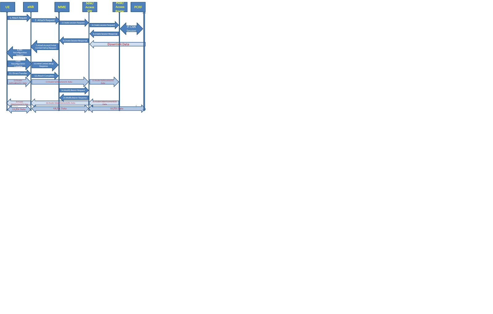 1. UE initiate Attach Request towards eNB to attach in the LTE network.
2. eNB derives the MME and sends Attach Request to MME in S1-MME Initial UE Message.
3. MME selects the SGW and sends Create Session Request towards SGW with EPS bearer information for default Bearer.
4. SGW creates the EPS bearer context and sends Create session Request to PGW with default EPS bearer information. Note: PGW selection done by MME and shared with SGW in Create session Request from MME. PDN GW performs an IP-CAN Session Establishment with PCRF. The PCRF may modify the APN-AMBR and the QoS parameters (QCI and ARP) associated with the default bearer in the response to the PDN GW.
5. PGW creates EPS Bearer Context table and generates Create Session Response towards SGW. PGW initiates the Charing activities for the EPS bearer. PGW also obtain the prefix from the external PDN through Diameter and shares the prefix info and Interface ID for an UE in the PAA(PDN Address) Informational Element of Create Session Request. Now PDN can sends the downlink packet for an UE but as the eNB information is not available the packet will get buffered at SGW. SGW might initiates Downlink indication towards MME.
6. SGW confirms the Default bearer creation and sends the Create Session Request with MME. SGW shares the prefix info and Interface ID for an UE in the PAA(PDN Address) Informational Element of Create Session Request.
7. MME creates the Bearer Context and sends Attach Accept in S1-MME Intial Context Setup Request to eNB. In the Attach Accept message, the MME does not include the IPv6 prefix within the PDN Address but shares the UE Interface ID to eNB.
8. eNB sends RRC Reconfiguration Request message to UE. If the UE receives an IPv6 interface identifier, it may wait for the Router Advertisement from the network with the IPv6 prefix information or it may send a Router Solicitation if necessary.
9. UE sends RRC Reconfiguration Complete message to eNB.
10. eNB sends the Initial Context Setup Response message to MME with eNB’s TEID(Tunnel Identifier) and IP address for downlink packet.
11. UE sends a Direct Transfer message to the eNodeB.
12. eNB sends the Attach Complete towards MME.
13. As UE knows the UL bearer information, now UE can sends the UL traffic. So UE initiates the Router Solicitation message towards network to get the Full IPv6 address. This packet is same as UL traffics.
14. MME initiates the Modify Bearer Request towards SGW to share the eNB’s information i.e. eNB’s TEID and IP address for downlink packet.
15. SGW updates the eNB information and sends Modify Bearer response towards MME.
16. Now SGW has the information of eNB, so the downlink packet can be delivered to UE. So the PGW response back with Router Advertisement message for a Router Solicitation message initiated by UE. The Router Advertisement message will have IPv6 prefix in it to make the Full IPv6 address. This Router Advertisement Message is carried as a DL packet. Now UE can make the full IPv6 address by using the Interface ID shared before by PGW and the IPv6 prefix shared in Router Advertisement message. •
References: – http://tools.ietf.org/html/draft-sarikaya-v6ops-prefix-delegation-09
– 23.402 (LTE Over View) 3gpp specification
– 29.274 (GTPv2-C) 3gpp specification
• P-GW allocates the IPv6 address to UE.
• This address allocation done through the Router Advertisement message.
• The Router Advertisement message will carry both Prefix and Interface ID for an UE.
• UE makes the FULL IPv6 address by using both Prefix and Interface ID
• There will be no DAD(Duplicate Address Detection) for IPv6 UE address as the UE IPv6 address is globally unique.
• As UE is in air interface and there is no IP Connectivity so there will be no DAD(Duplicate Address detection)
• But in between eNB-MME-SGW-PGW, DAD is available as there is a chance of duplicate Address. So DAD is applicable here.
2. eNB derives the MME and sends Attach Request to MME in S1-MME Initial UE Message.
3. MME selects the SGW and sends Create Session Request towards SGW with EPS bearer information for default Bearer.
4. SGW creates the EPS bearer context and sends Create session Request to PGW with default EPS bearer information. Note: PGW selection done by MME and shared with SGW in Create session Request from MME. PDN GW performs an IP-CAN Session Establishment with PCRF. The PCRF may modify the APN-AMBR and the QoS parameters (QCI and ARP) associated with the default bearer in the response to the PDN GW.
5. PGW creates EPS Bearer Context table and generates Create Session Response towards SGW. PGW initiates the Charing activities for the EPS bearer. PGW also obtain the prefix from the external PDN through Diameter and shares the prefix info and Interface ID for an UE in the PAA(PDN Address) Informational Element of Create Session Request. Now PDN can sends the downlink packet for an UE but as the eNB information is not available the packet will get buffered at SGW. SGW might initiates Downlink indication towards MME.
6. SGW confirms the Default bearer creation and sends the Create Session Request with MME. SGW shares the prefix info and Interface ID for an UE in the PAA(PDN Address) Informational Element of Create Session Request.
7. MME creates the Bearer Context and sends Attach Accept in S1-MME Intial Context Setup Request to eNB. In the Attach Accept message, the MME does not include the IPv6 prefix within the PDN Address but shares the UE Interface ID to eNB.
8. eNB sends RRC Reconfiguration Request message to UE. If the UE receives an IPv6 interface identifier, it may wait for the Router Advertisement from the network with the IPv6 prefix information or it may send a Router Solicitation if necessary.
9. UE sends RRC Reconfiguration Complete message to eNB.
10. eNB sends the Initial Context Setup Response message to MME with eNB’s TEID(Tunnel Identifier) and IP address for downlink packet.
11. UE sends a Direct Transfer message to the eNodeB.
12. eNB sends the Attach Complete towards MME.
13. As UE knows the UL bearer information, now UE can sends the UL traffic. So UE initiates the Router Solicitation message towards network to get the Full IPv6 address. This packet is same as UL traffics.
14. MME initiates the Modify Bearer Request towards SGW to share the eNB’s information i.e. eNB’s TEID and IP address for downlink packet.
15. SGW updates the eNB information and sends Modify Bearer response towards MME.
16. Now SGW has the information of eNB, so the downlink packet can be delivered to UE. So the PGW response back with Router Advertisement message for a Router Solicitation message initiated by UE. The Router Advertisement message will have IPv6 prefix in it to make the Full IPv6 address. This Router Advertisement Message is carried as a DL packet. Now UE can make the full IPv6 address by using the Interface ID shared before by PGW and the IPv6 prefix shared in Router Advertisement message. •
References: – http://tools.ietf.org/html/draft-sarikaya-v6ops-prefix-delegation-09
– 23.402 (LTE Over View) 3gpp specification
– 29.274 (GTPv2-C) 3gpp specification


